

CanandDevice
Message/wire format spec, version 2024-offseason.
The device spec for Redux products will not change in a backwards-incompatible fashion in-season, from the first official release for a given year until after the FIRST Championship.
Summary of the CAN address scheme and packet format
Section titled “Summary of the CAN address scheme and packet format”Redux CAN devices conform to the 29-bit FRC CAN message address scheme, with a very specific rearrangement of the API identifier/class field.
A full CAN arbitration id that actually gets put on the bus can be broken down into four components:
- A 5 bit device type (devType) that is product specific (the Canandmag is 7 for “gear tooth sensor”)
- An 8-bit manufacturer code unique to each vendor (the Redux code is 14 in decimal or 0xE)
- 10 bits of API identifier
- A 6-bit device number (devId) that is user-configurable so you can have multiple of a device on a bus — this is what the “CAN ID” in robot code and vendor tuners usually refer to.
The WPILib docs elaborates on this in a bit more detail. Of note is that it breaks down the 10-bit API identifier into a 6-bit API class and 4-bit API index.
Redux products break it down into a 2 bit API page (currently always 0) and an 8 bit API index (apiIndex).
The breakdown can be seen in the diagram provided below for a Party Mode packet sent to Canandmag device 4:
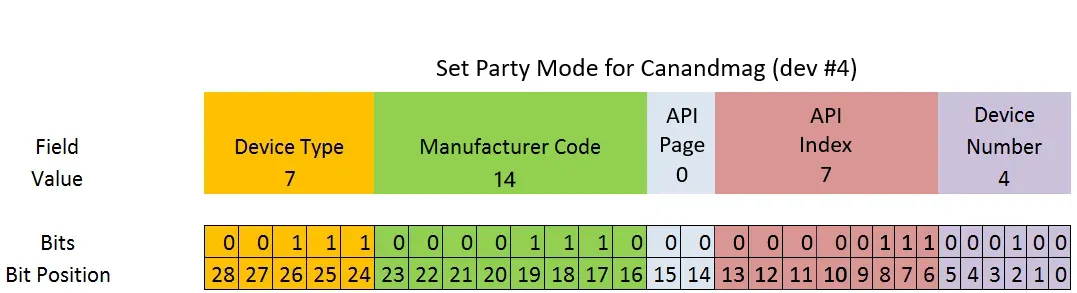
Based on diagram from: WPILib Docs
Summary of the settings scheme
Section titled “Summary of the settings scheme”Redux CAN device have a series of settings that are up to 6 bytes in length, that are managed using the SET_SETTING, SETTING_COMMAND and REPORT_SETTING messages. Exact format and functionality of each setting field is generally device dependent.
Sending a SET_SETTING packet, will trigger a REPORT_SETTING message as a reply to confirm the transaction and success or failure. The SETTING_COMMAND packet can be used to either report settings, reset to default settings, or perform other device-specific actions.
All value fields are default unsigned little-endian unless otherwise specified.
This document uses the following conventions for notating field types:
| Type | Description |
|---|---|
| bool | Single-bit boolean |
| float:24 | IEEE 754 single-precision float with the least significant 8 bits of mantissa stripped to fit in 3 bytes |
| float:32 | IEEE 754 single-precision (32-bit) float |
| float:64 | IEEE 754 double-precision (64-bit) float |
| uintN_t | Unsigned integer of bit width N |
| intN_t | Signed integer of bit width N |
| padN_t | N bits of padding bits that should be left zero. |
| uint8_t[N] | N bytes of a byte array |
Additionally, when literals are specified for default values,
trueandfalseare defined as bit values 1 and 0 respectively- For a byte array specified as
{0x1, 0x2, 0x3, 0x4}the first (index zero) byte is 0x1 and the last is 0x4.
Messages
Section titled “Messages”These are the definitions of messages sent over CAN, USB, or other encapsulation mechanisms.
Message summary:
| API Index | Message | Description |
|---|---|---|
| 0xb | ENUMERATE | Device enumerate response |
| 0x7 | PARTY_MODE | Party mode |
| 0x6 | STATUS | Status frame |
| 0x5 | CLEAR_STICKY_FAULTS | Clear device sticky faults |
| 0x4 | REPORT_SETTING | Setting value report from device |
| 0x3 | SET_SETTING | Update setting on device |
| 0x2 | SETTING_COMMAND | Setting control command |
ENUMERATE
Section titled “ENUMERATE”Sent by the device upon an enumerate request, or every 100 milliseconds if the device is stuck in OTA bootloader.
The exact format of enumerate request may vary between communication mediums:
- For a CAN bus an enumerate request is a message with an extended (29-bit) arbitration ID of 0xE0000
Properties
| Property | Value |
|---|---|
| API Index | 0xb |
| Message length | 8 bytes |
| Transmission direction | Device -> robot |
Signals
| Signal name | Signal type | Optional | Description |
|---|---|---|---|
serial | uint8_t[6] | ❌ | Device-unique serial number |
is_bootloader | bool | ❌ | Device is in bootloader. |
reserved | pad15_t | ❌ | Reserved |
PARTY_MODE
Section titled “PARTY_MODE”Configures party mode to the device.
Non-zero values will prompt the onboard RGB LED of the device to cycle various colors to help identify where it physically sits on a robot.
A zero value stops the cycling.
Properties
| Property | Value |
|---|---|
| API Index | 0x7 |
| Minimum message length | 1 bytes |
| Maximum message length | 8 bytes |
| Transmission direction | Robot -> device |
Signals
| Signal name | Signal type | Optional | Description |
|---|---|---|---|
party_level | uint8_t | ❌ | Party level. 0 disables the strobe, whereas each increased value up to 10 increases strobe period by 50 ms. |
STATUS
Section titled “STATUS”Periodic frame containing status information about the device.
Typically this contains active and sticky faults as well as environmental information such as device temperature. The actual composition of this message will vary from device to device, but it is guaranteed to be 8 bytes long. Consult individual device documentation pages for more information.
This frame cannot be disabled.
The period at which this message is broadcasted at is controlled by the STATUS_FRAME_PERIOD setting.
Properties
| Property | Value |
|---|---|
| API Index | 0x6 |
| Message length | 8 bytes |
| Transmission direction | Device -> robot |
| Frame period setting | STATUS_FRAME_PERIOD |
| Default frame period | 1000 milliseconds |
Signals
| Signal name | Signal type | Optional | Description |
|---|---|---|---|
dev_specific | uint8_t[8] | ❌ | Device-specific status data. See device pages for more information. |
CLEAR_STICKY_FAULTS
Section titled “CLEAR_STICKY_FAULTS”Sent to device to clear all sticky faults (sets the sticky faults to 0 until faults become active again)
Properties
| Property | Value |
|---|---|
| API Index | 0x5 |
| Minimum message length | 0 bytes |
| Maximum message length | 8 bytes |
| Transmission direction | Robot -> device |
REPORT_SETTING
Section titled “REPORT_SETTING”Sent to report a setting value from the device.
These messages can be triggered by:
- A setting change via SET_SETTING
- The fetch setting value SETTING_COMMAND
- A reset to factory default SETTING_COMMAND
- Other device-specific mechanisms including device-specific setting commands
The setting flags include information on whether or not the setting set was successful as well as the setting data that was sent.
Sent after a setting change via or on the fetch settings and factory reset. Setting changes (as of v2024) will always include the “settings flag” field.
Properties
| Property | Value |
|---|---|
| API Index | 0x4 |
| Message length | 8 bytes |
| Transmission direction | Device -> robot |
Signals
| Signal name | Signal type | Optional | Description |
|---|---|---|---|
address | Setting index | ❌ | Setting index to write to |
value | setting_data | ❌ | 6-byte setting value |
flags | setting_report_flags | ❌ | Setting receive status |
SET_SETTING
Section titled “SET_SETTING”Sent to device to change a setting by address.
If the setting exists, a REPORT_SETTING packet will be sent in reply, with the data of the setting echoed back and information on whether or not the setting set succeeded.
Properties
| Property | Value |
|---|---|
| API Index | 0x3 |
| Message length | 8 bytes |
| Transmission direction | Robot -> device |
Signals
| Signal name | Signal type | Optional | Description |
|---|---|---|---|
address | Setting index | ❌ | Setting index to write to |
value | setting_data | ❌ | 6-byte setting value |
flags | setting_flags | ❌ | Setting flags |
SETTING_COMMAND
Section titled “SETTING_COMMAND”Sent to the device to operate on the settings subsystem.
Devices may add their own setting commands but they will typically at least have:
- Fetch all settings (id 0x0)
- Reset all applicable settings to factory default (id 0x1)
- Fetch setting value (id 0x2)
Most setting commands (e.g. reset to factory default and get all settings) are allowed to have a data length code of 1, however, the fetch setting value command requires a data length of at least 2 bytes to also specify the setting index to fetch.
The most typical use case is likely to fetch a specific setting value; to fetch firmware version for example one might send this packet
with the payload {0x2, 0x6} and wait for a REPORT_SETTING to report the setting.
Properties
| Property | Value |
|---|---|
| API Index | 0x2 |
| Minimum message length | 1 bytes |
| Maximum message length | 8 bytes |
| Transmission direction | Robot -> device |
Signals
| Signal name | Signal type | Optional | Description |
|---|---|---|---|
control_flag | SETTING_COMMAND (Enum) | ❌ | Setting command index |
setting_index | Setting index | ✅ | Setting index to fetch |
Settings
Section titled “Settings”Settings hold and manipulate the configuration of the device.
Most settings are saved to non-volatile flash, are saved on device reboot, are considered both readable and writable, and will be reset to a default value when a reset to factory default setting command is issued.
Some settings are read-only as they contain device or firmware specific information such as serial number or firmware version.
Other settings may be write-only as they command the device to do something specific; e.g. update an offset. In practice, settings get used whenever an infrequent (non-periodic) call-response architecture makes sense spec-wise.
Each setting is associated with an 8-bit unsigned setting index byte. Setting data is encoded as 48-bit (6 byte) fields. Both setting index and encoded setting data are sent in SET_SETTING and REPORT_SETTING messages, whereas the FETCH_SETTING_VALUE setting command only requires an index.
If a type associated with a setting is less than 48 bits wide (e.g. a float32), the rest of the data field during encode/decode can be assumed to be padding and left as zero.
Setting summary:
| Setting index | Name | Type | Default value | Readable | Writable | Resets to factory default | Description |
|---|---|---|---|---|---|---|---|
| 0x8 | DEVICE_TYPE | uint16_t | n/a | ✅ | ❌ | ❌ | Device-specific type identifier |
| 0x6 | FIRMWARE_VERSION | firmware_version | n/a | ✅ | ❌ | ❌ | Firmware version |
| 0x5 | SERIAL_NUMBER | uint8_t[6] | n/a | ✅ | ❌ | ❌ | Serial number |
| 0x4 | STATUS_FRAME_PERIOD | status_frame_period | 1000 | ✅ | ✅ | ✅ | Status frame period (ms) |
| 0x3 | NAME_2 | uint8_t[6] | [0x0, 0x0, 0x0, 0x0, 0x0, 0x0] | ✅ | ✅ | ✅ | device_name[12:17] |
| 0x2 | NAME_1 | uint8_t[6] | [0x44, 0x65, 0x76, 0x69, 0x63, 0x65] | ✅ | ✅ | ✅ | device_name[6:11] |
| 0x1 | NAME_0 | uint8_t[6] | [0x43, 0x61, 0x6e, 0x61, 0x6e, 0x64] | ✅ | ✅ | ✅ | device_name[0:5] |
| 0x0 | CAN_ID | can_device_id | 0 | ✅ | ✅ | ❌ | CAN Device ID |
DEVICE_TYPE
Section titled “DEVICE_TYPE”Read-only device type identifier.
If multiple types of device share the same FRC-CAN device class, e.g. two device variants that do similar things but may or may not have the same message API, this setting can be used to disambiguate between them.
| Property | Value |
|---|---|
| Setting index | 0x8 |
| Type | uint16_t |
| Default value | n/a |
| Readable | ✅ |
| Writable | ❌ |
| Resets on factory default | ❌ |
FIRMWARE_VERSION
Section titled “FIRMWARE_VERSION”Read-only setting value of the device’s firmware version.
| Property | Value |
|---|---|
| Setting index | 0x6 |
| Type | firmware_version |
| Default value | n/a |
| Readable | ✅ |
| Writable | ❌ |
| Resets on factory default | ❌ |
SERIAL_NUMBER
Section titled “SERIAL_NUMBER”Read-only setting of the device’s serial number.
| Property | Value |
|---|---|
| Setting index | 0x5 |
| Type | uint8_t[6] |
| Default value | n/a |
| Readable | ✅ |
| Writable | ❌ |
| Resets on factory default | ❌ |
STATUS_FRAME_PERIOD
Section titled “STATUS_FRAME_PERIOD”Period between the transmission of STATUS messages in milliseconds. This frame cannot be disabled (as Alchemist uses it to detect devices).
| Property | Value |
|---|---|
| Setting index | 0x4 |
| Type | status_frame_period |
| Default value | 1000 |
| Readable | ✅ |
| Writable | ✅ |
| Resets on factory default | ✅ |
NAME_2
Section titled “NAME_2”Last 6 bytes of the name field. Having a null byte will terminate the name field at that byte. All 6 bytes can be non-null and the name will be 18 characters long.
| Property | Value |
|---|---|
| Setting index | 0x3 |
| Type | uint8_t[6] |
| Default value | [0x0, 0x0, 0x0, 0x0, 0x0, 0x0] |
| Readable | ✅ |
| Writable | ✅ |
| Resets on factory default | ✅ |
NAME_1
Section titled “NAME_1”Middle 6 bytes of the device name. Having a null byte will terminate the name field at that byte.
| Property | Value |
|---|---|
| Setting index | 0x2 |
| Type | uint8_t[6] |
| Default value | [0x44, 0x65, 0x76, 0x69, 0x63, 0x65] |
| Readable | ✅ |
| Writable | ✅ |
| Resets on factory default | ✅ |
NAME_0
Section titled “NAME_0”First 6 bytes of the device name. Having a null byte will terminate the name field at that byte.
| Property | Value |
|---|---|
| Setting index | 0x1 |
| Type | uint8_t[6] |
| Default value | [0x43, 0x61, 0x6e, 0x61, 0x6e, 0x64] |
| Readable | ✅ |
| Writable | ✅ |
| Resets on factory default | ✅ |
CAN_ID
Section titled “CAN_ID”Sets the 6-bit device id, ranging from 0 to 63. This allows multiple of a device to share a bus. Defaults to 0 but does not reset on factory resets.
| Property | Value |
|---|---|
| Setting index | 0x0 |
| Type | can_device_id |
| Default value | 0 |
| Readable | ✅ |
| Writable | ✅ |
| Resets on factory default | ❌ |
Data types associated with messages and/or settings.
frame_period
Section titled “frame_period”Frame period associated with some periodic data or status frame. 1 LSB equals 1 ms of period, and setting the period to 0 will disable the corresponding frame.
| Property | Value |
|---|---|
| Base type | uint |
| Bit width | 16 |
| Minimum value | 0 |
| Maximum value | 65535 |
| Default value | 0 |
| Conversion factor | 1 LSB = 1/1000 seconds |
status_frame_period
Section titled “status_frame_period”Frame period specific to the STATUS frame, as status frames cannot be set to 0 and disabled.
| Property | Value |
|---|---|
| Base type | uint |
| Bit width | 16 |
| Minimum value | 1 |
| Maximum value | 16383 |
| Default value | 1000 |
| Conversion factor | 1 LSB = 1/1000 seconds |
can_device_id
Section titled “can_device_id”The CAN device id used by the device. As specified by the FRC-CAN spec, this comprises the least significant 6 bits of the CAN id.
| Property | Value |
|---|---|
| Base type | uint |
| Bit width | 8 |
| Minimum value | 0 |
| Maximum value | 63 |
| Default value | 0 |
setting_flags
Section titled “setting_flags”Information set on the SET_SETTING message.
Setting the ephemeral bit makes the setting not save to non-volatile memory and not persist on reboot, if applicable.
Sending multiple messages with the synch hold message will queue them for application on device until a message with the bit unset and the number of messages expected to be in the queue (in synch_msg_count) is set.
If the number of settings in the queue equals the number of settings in synch_message_count, all settings are applied and a report settings message with the commit_success bit is set. Otherwise, none of them are applied and the commit success bit is unset.
Original Canandmags do not support the synch hold mechanism.
| Property | Value |
|---|---|
| Base type | struct |
| Bit width | 8 |
Signals:
| Name | Type | Default value | Description |
|---|---|---|---|
ephemeral | bool | false | Whether the setting should be set ephemeral |
synch_hold | bool | false | Whether the setting should be held until the next synch barrier |
reserved_0 | pad2_t | 0 | Reserved |
synch_msg_count | uint4_t | 0 | Synch message count |
setting_report_flags
Section titled “setting_report_flags”Bits set by the REPORT_SETTING message to indicate success or failure
| Property | Value |
|---|---|
| Base type | bitset |
| Bit width | 8 |
Flags:
| Flag index | Flag name | Default value | Description |
|---|---|---|---|
| 0 | set_success | 0 | Whether the setting set/fetch was successful |
| 1 | commit_success | 0 | Whether the setting synch commit was successful |
firmware_version
Section titled “firmware_version”Firmware version reported by the device.
| Property | Value |
|---|---|
| Base type | struct |
| Bit width | 32 |
Signals:
| Name | Type | Default value | Description |
|---|---|---|---|
firmware_patch | uint8_t | 0 | Firmware version patch number |
firmware_minor | uint8_t | 0 | Firmware version minor number |
firmware_year | uint16_t | 0 | Firmware version year |
rfloat32
Section titled “rfloat32”An IEEE single-precision float32 that cannot be NaN or infinite.
| Property | Value |
|---|---|
| Base type | float |
| Bit width | 32 |
| Minimum value | n/a |
| Maximum value | n/a |
| Default value | 0 |
pfloat32
Section titled “pfloat32”An IEEE single-precision float32 that must be non-negative but may be NaN or infinite.
| Property | Value |
|---|---|
| Base type | float |
| Bit width | 32 |
| Minimum value | 0.0 |
| Maximum value | n/a |
| Default value | 0 |
prfloat32
Section titled “prfloat32”An IEEE single-precision float32 that must be non-negative AND cannot be NaN or infinite.
| Property | Value |
|---|---|
| Base type | float |
| Bit width | 32 |
| Minimum value | 0.0 |
| Maximum value | n/a |
| Default value | 0 |
lfloat32
Section titled “lfloat32”An IEEE single-precision float32 constrained between 0 and 1 inclusive.
| Property | Value |
|---|---|
| Base type | float |
| Bit width | 32 |
| Minimum value | 0.0 |
| Maximum value | 1.0 |
| Default value | 0 |
Enums associated with messages and/or settings. The backing type is always an unsigned int of some specified width.
SETTING_COMMAND
Section titled “SETTING_COMMAND”These are setting commands issued via the SETTING_COMMAND message. The fetch setting command and reset factory settings command are common to all Redux devices.
| Property | Value |
|---|---|
| Bit width | 8 |
| Default enum |
Enum variants:
| Enum index | Variant name | Description |
|---|---|---|
| 0x0 | FETCH_SETTINGS | Fetch all settings from device via a series of REPORT_SETTING messages of all indexes |
| 0x1 | RESET_FACTORY_DEFAULT | Reset all resettable settings to factory default, and broadcast all setting values via REPORT_SETTING messages. |
| 0x2 | FETCH_SETTING_VALUE | Requests to fetch a single setting from device, with its value reported via the REPORT_SETTING message. This requires the use of the second byte to specify the setting index to fetch. |