
Canandcolor Alchemist Guide
The Canandcolor can be configured from the Alchemist Configuration Tool, which provides an easy to use UI for configuring the sensor.
Overview
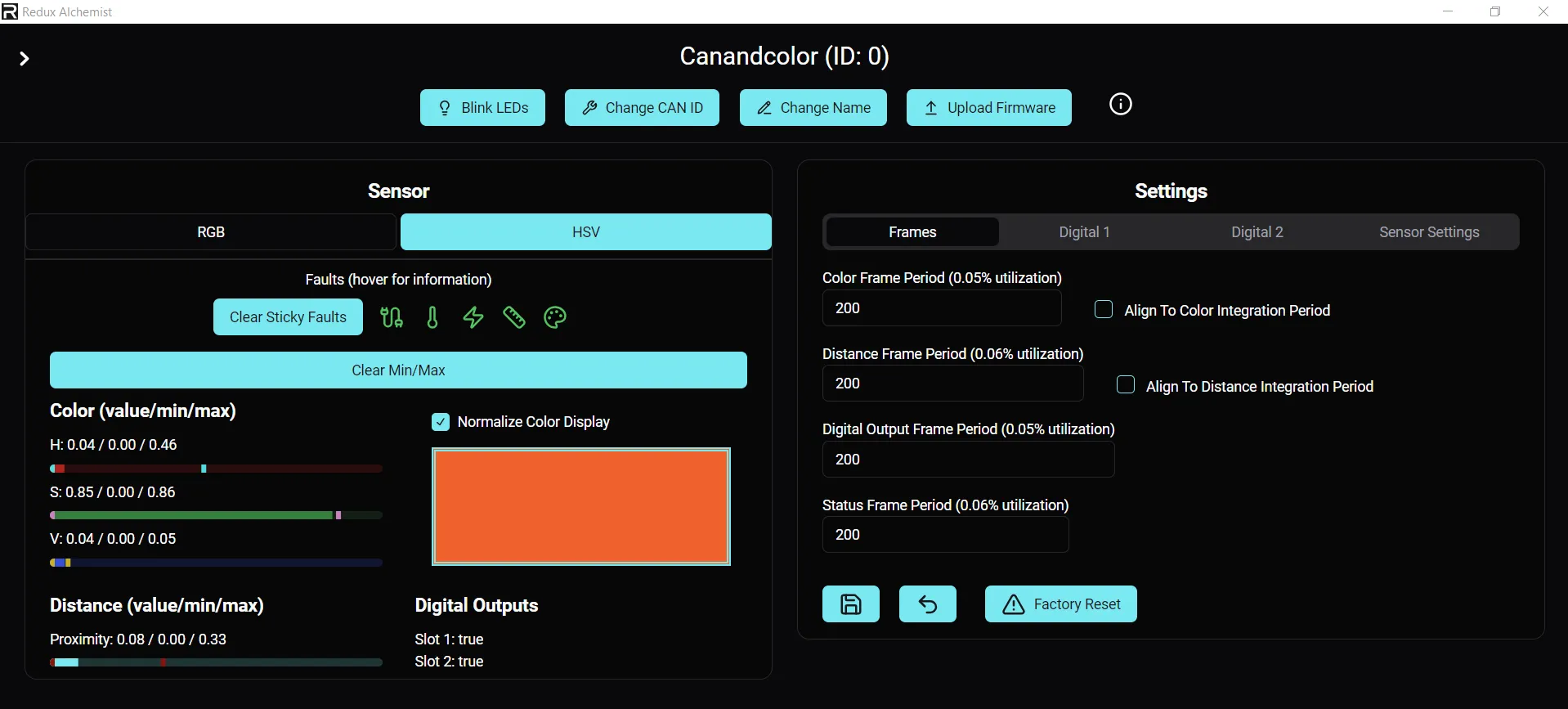
Section titled “Overview”Once connected, the canandcolor can be selected from the list of devices. In addition to general device options, like blinking the LED and changing the CAN ID, there are other settings that can be adjusted.
Sensor Card
Section titled “Sensor Card”The sensor card contains information about the onboard sensors on the Canandcolor.
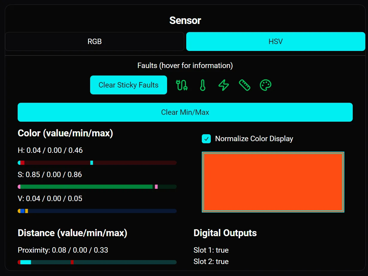
Below the faults are the sensor outputs. Color outputs can be toggled between RGB (Red Green Blue) and HSV (Hue Saturation Value) using the toggle at the top of the card.
All outputs display the current value, the minimum value that has been observed, and the maximum value that has been observed. These minimum and maximum values are useful for creating thresholds, and can be cleared using the Clear Min/Max button.
In addition, a color display output is shown on the right of the card. Since the sensor is commonly used in situations where the true color output is dark, a Normalize Color Display option allows the color display magnitude to be normalized, so that the color output will show a color.
Below the color display is the Digital Output statuses. True indicates that the output is HIGH, false indicates that the output is LOW.
Setting Card
Section titled “Setting Card”The setting card contains all of the device specific settings in the canandcolor. For the canandcolor, this is made up of 4 tabs.
Frames
Section titled “Frames”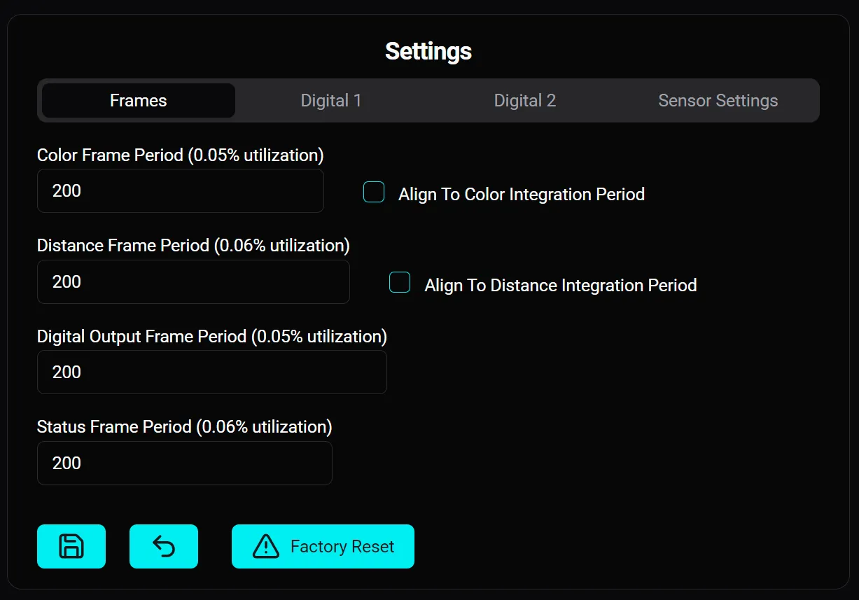
The frame tab lets you set the transmission rate of each of the sensor’s CAN frames in milliseconds.
The color and proximity frames can optionally be aligned to the integration period of the sensor itself, so that the sensor automatically emits new packets when data is sampled from the underlying sensor.
Digital Output
Section titled “Digital Output”There are two digital output setting tabs corresponding to the two digital output lines from the sensor. The layout of both are identical, except for Digout 2 which allows setting to “PWM” mode with a selector for which channel is transmitted over PWM.
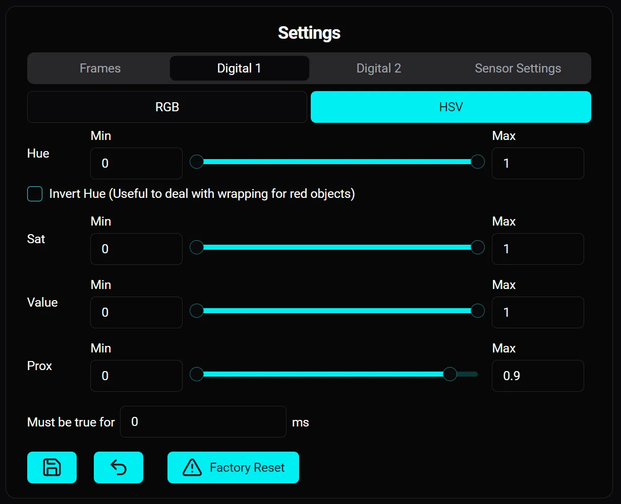
The minimum and maximum value of each input can be adjusted via the slider or number input boxes. The digital output will become True when all of the conditions within the sliders are met.
In addition, the minimum amount of time in milliseconds that the conditions must be true in order for the digital output to be true can be set. This can be useful for “de-bouncing”, preventing the condition from being set to true if the conditions are only met for a brief amount of time.
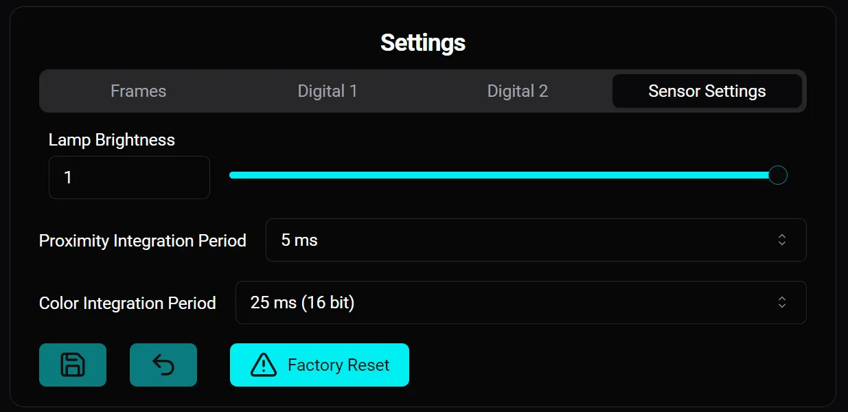
Sensor Settings
Section titled “Sensor Settings”The sensor settings tab lets you set the onboard LED brightness, the proximity sensor integration period, and the color sensor integration period.