

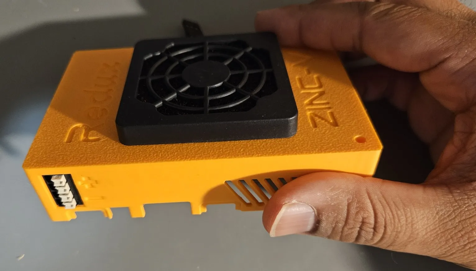
Assembling the Orange Pi 5 Case
Redux provides two styles of case, one with an internal Zinc-V that requires soldering, and one with a locking USB-C port to support an external Zinc-V without any soldering. An “unvented” version is available for the case with an external Zinc-V, for users who want to avoid having any exposed points of ingress.
An Orange Pi 5 with 1 processing camera and 1 driver view camera on it will perform comfortably without thermal throttling on the sealed case, when heatsunk inside the case. In high ambient temperatures, or if you have more than 2 cameras, the vented case will perform better.
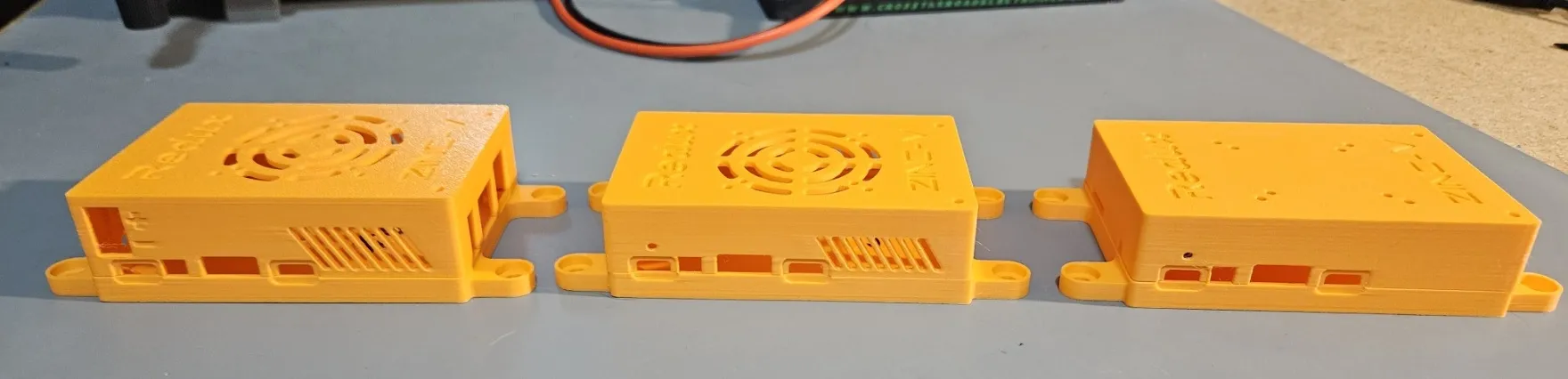
From left to right: the Internal Case, External Vented Case, and the External Unvented Case.
What You Will Need
Section titled “What You Will Need”You will need the following materials:
- Orange Pi 5
- Zinc-V
- Printed casing of your choice
- 2pcs 4-40 x 5/16” screws
- 4pcs 4-40 nuts or locknuts (recommended)
- Small screwdriver
- Short 2 or 3-pin servo cable with “dupont” connector (for Internal Case)
- 2pcs 4-40 x 1-1/8” screws (for External Case) or 2pcs 4-40 x 1-1/4” screws (for Internal Case)
- Locking USB-C cable (for External Case)
Optional materials:
- Heatsink (recommended for all cases)
- 5010 or 4010 fan
- 5010 or 4010 fan filter
- Fan attachment screws
- 2pcs 4-40 x 3/16” screws and 2pcs 4-40 nuts or locknuts (for Internal Case)
Printing
Section titled “Printing”The cases can be printed on almost any 3D printer, without support material. Cases can be printed from PLA, but PETG may perform better over long periods of time due to its heat and UV resistance.
Internal Zinc-V Case Assembly
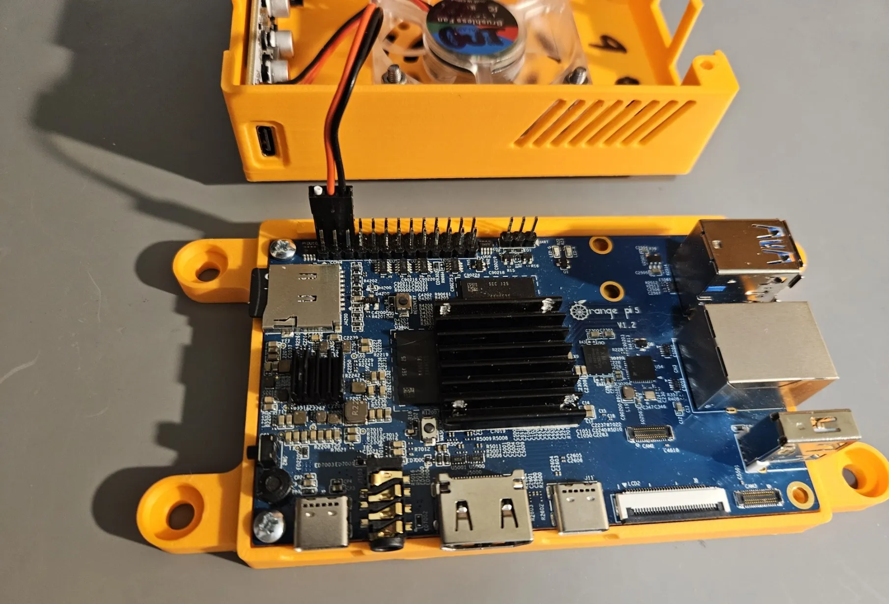
Section titled “Internal Zinc-V Case Assembly”First, get the parts together as shown below.
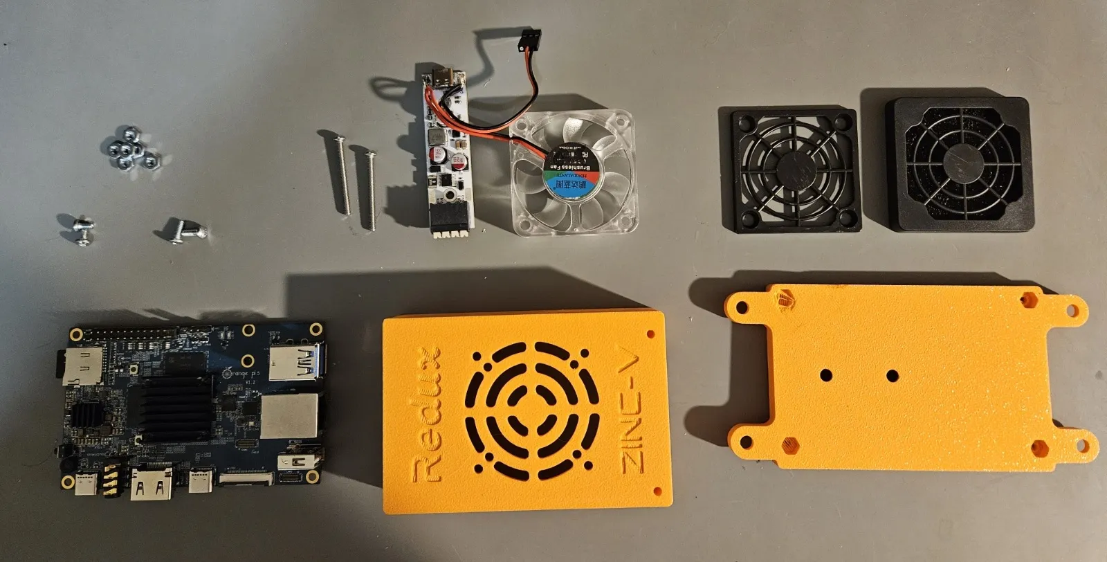
Not pictured are the fan install screws, as these will vary based on the fan thickness and whether you have a filter or not. Any M3 or 4-40 screw + nuts of sufficient length should work fine.
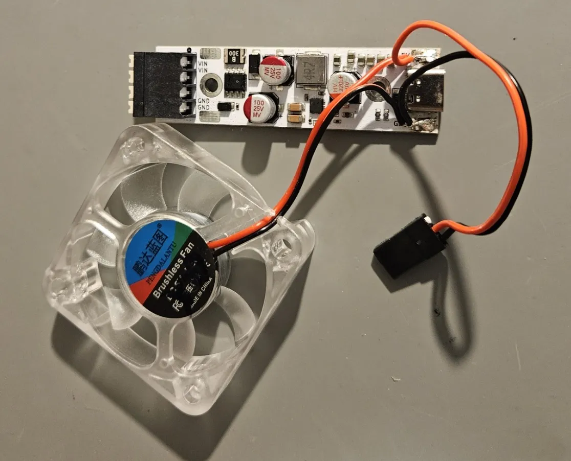
Next, solder the fan and the power lead to the Zinc-V. To do this, first tin the pads on the Zinc-V with some solder. Then, strip the leads of the fan and the power cable. Here, you’ll see we have used a 3-pin servo cable and trimmed the white wire short. Twist the 5V (red) leads together and twist the GND (black) leads together. Tin the wires with some solder. Finally, press the tinned wires to the pads with your soldering iron. The finished product should look like the image below.
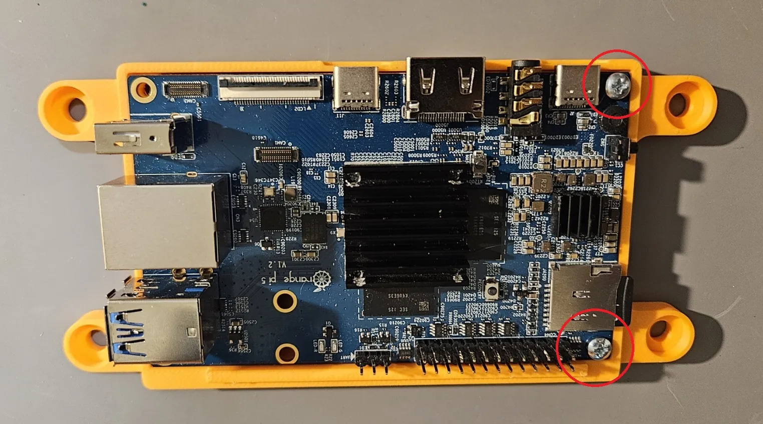
Next, take your Orange Pi 5 and place it into the casing as shown.
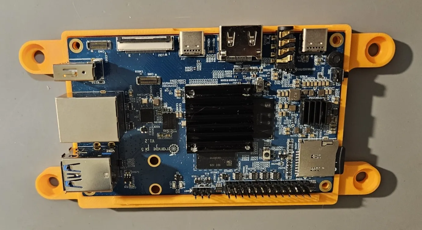
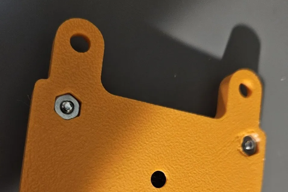
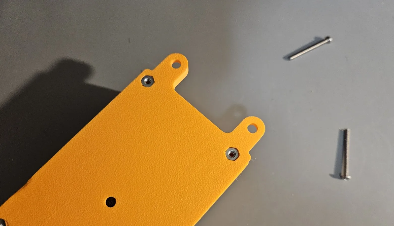
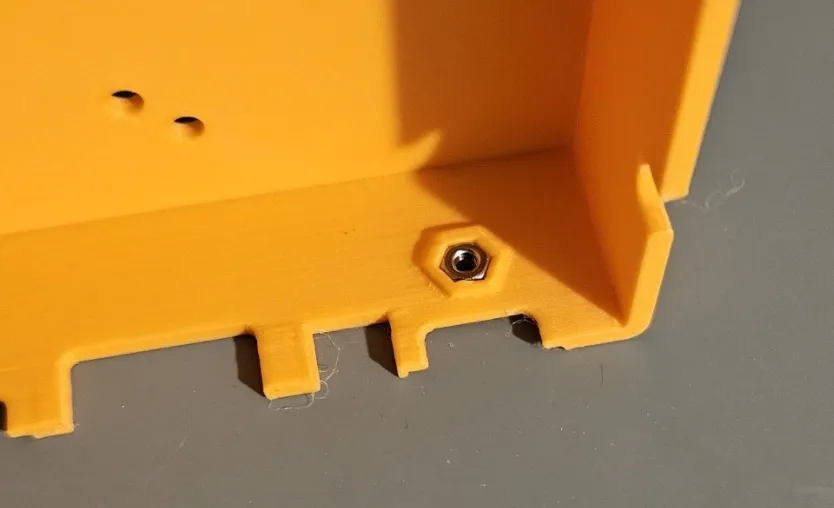
Use the two 4-40 x 5/16” screws and 2 4-40 nuts to screw it into the base on the indicated holes. The nuts will need to be inserted into the pockets on the bottom side.
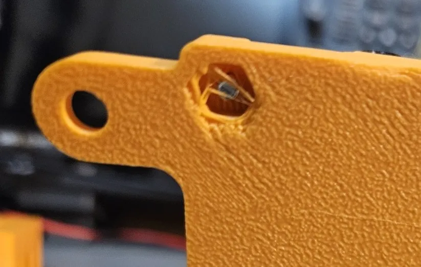
When you poke the screws through the holes in the case, you might need to break a small seal of plastic (placed there to improve printability). Some “schmoo” might be present in the hole. Use a screwdriver or flush cutter to clean it up if necessary to make a better fit for the nut.
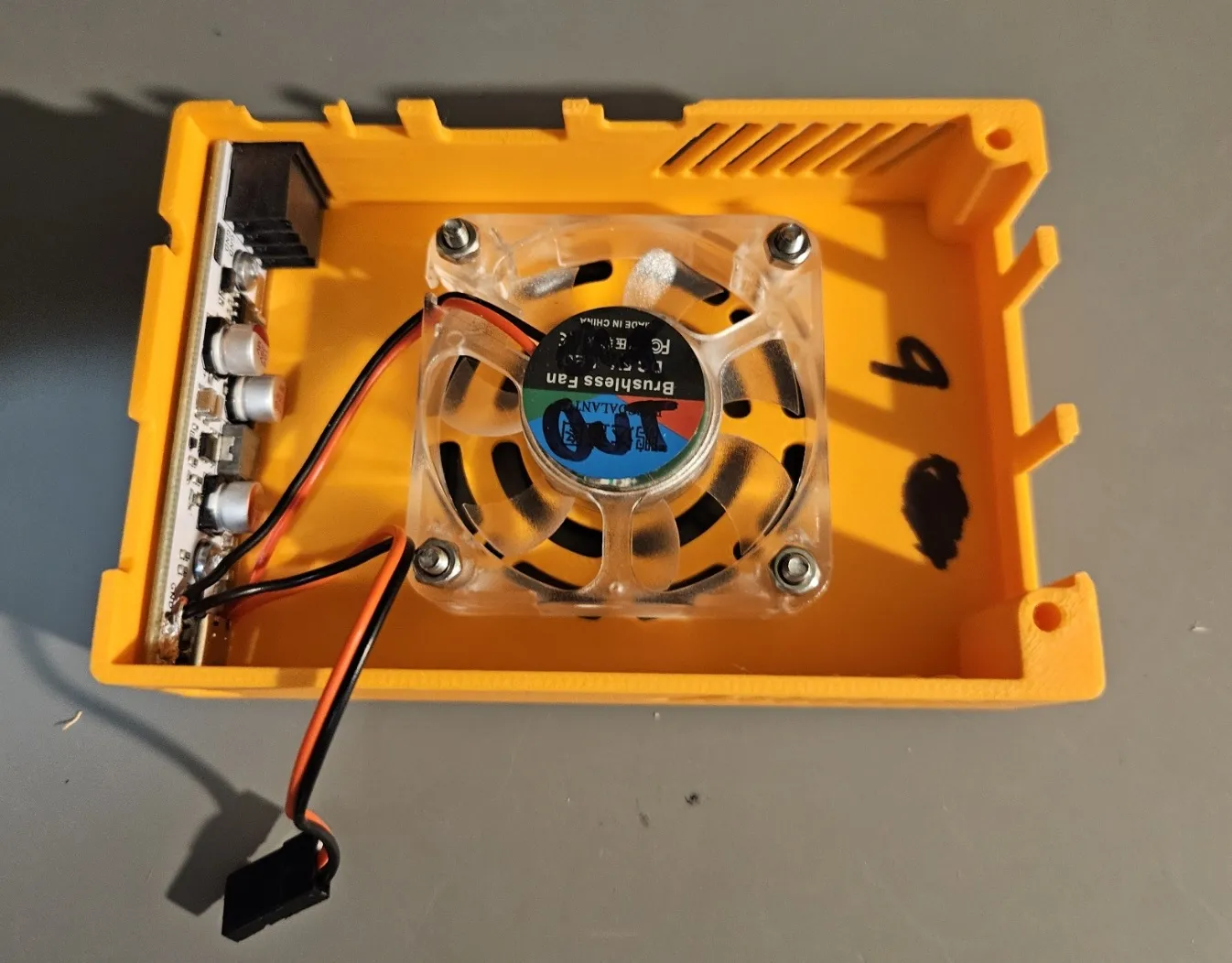
Next, we’ll install the Zinc-V and the fan into the top side of the case. Tilt the Zinc-V into the terminal block hole as shown. Then, push it down until the USB-C port clicks into the hole in the side of the case.
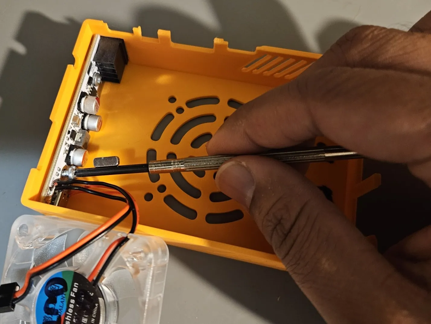
You can now use the 2 4-40 x 1/4” screws and 4-40 nuts to secure the Zinc-V via its mounting holes. I consider this to be optional, as most printers will hold the Zinc-V in place with only the snap fit. A small magnet can be attached to the screwdriver as shown to help hold the screw while guiding it into the hole.
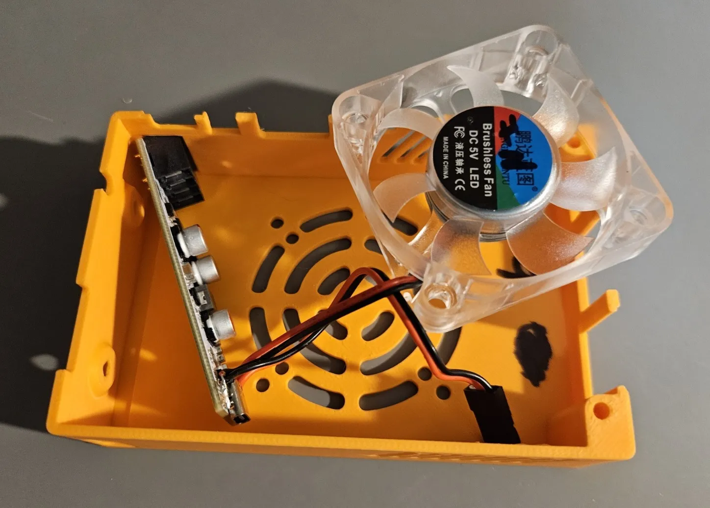
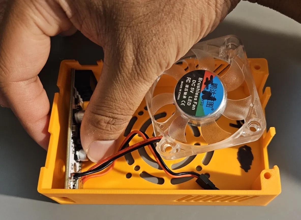
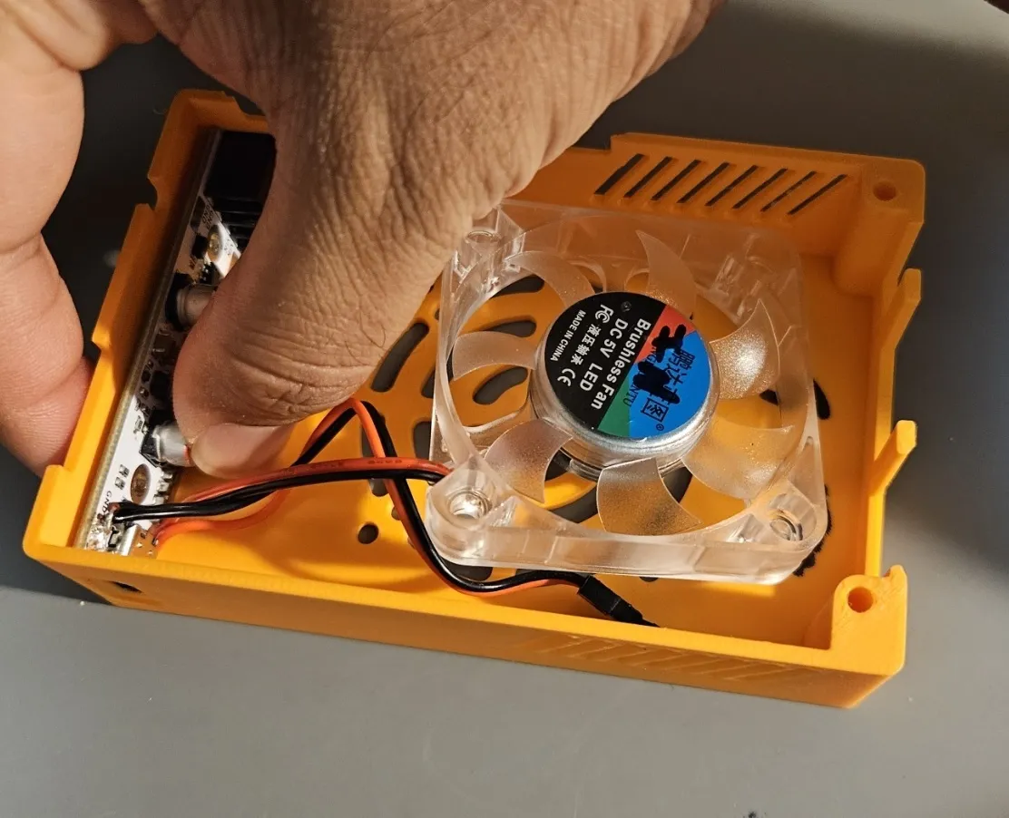
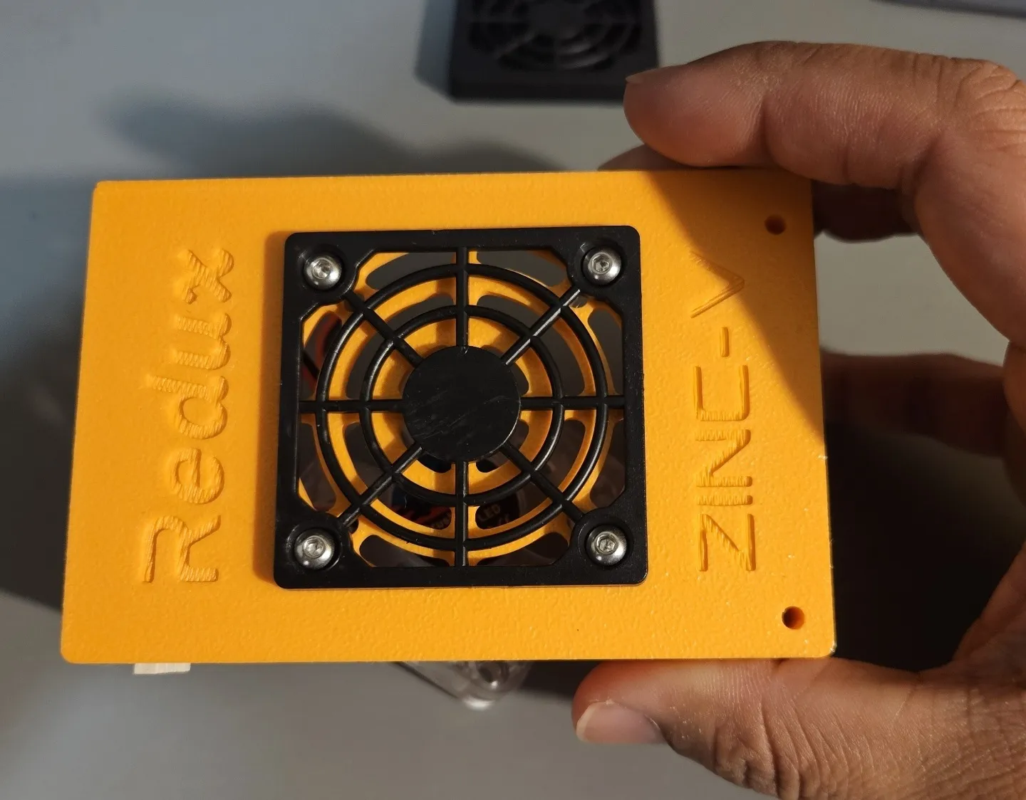
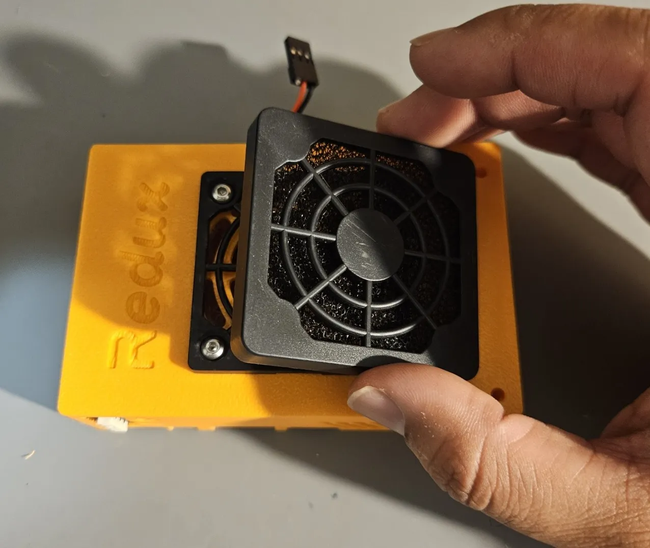
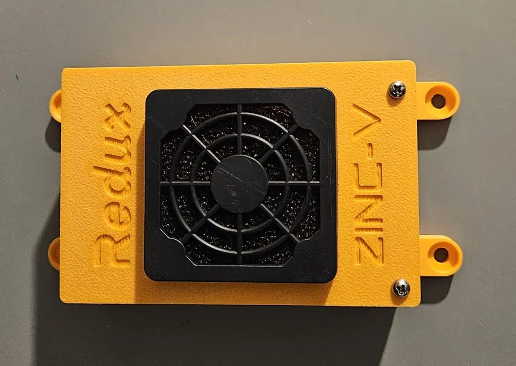
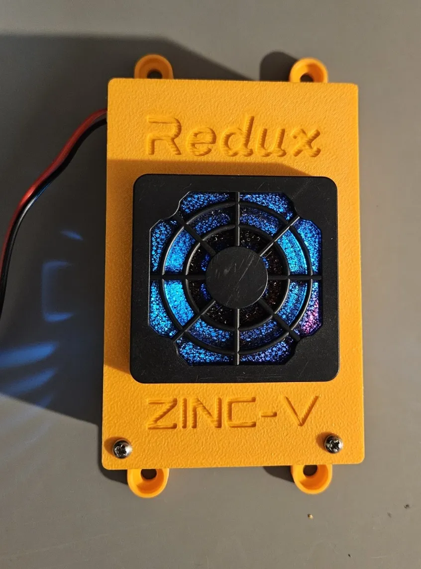
Now we will mount the fan. If you are using a filter, you’ll need to take the lower part of the grill and place it on the top of the case, with the fan on the inside. Make sure to attach the fan well, ideally with locknuts, as removing the filter later can be tricky.
If you are using a filter, snap it on as shown.
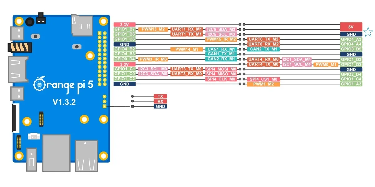
Now we can plug the top case into the Orange Pi. Pay close attention to which pins you are plugging into. The red wire should go to 5V, and the black wire should go to GND. This lead can also be soldered, but do so at your own risk - this can make it annoying to swap out hardware if needed.
Source: orangepi.org
Test your setup now by applying 12V to the input of the Zinc-V. You should see the fan and OrangePi turn on.
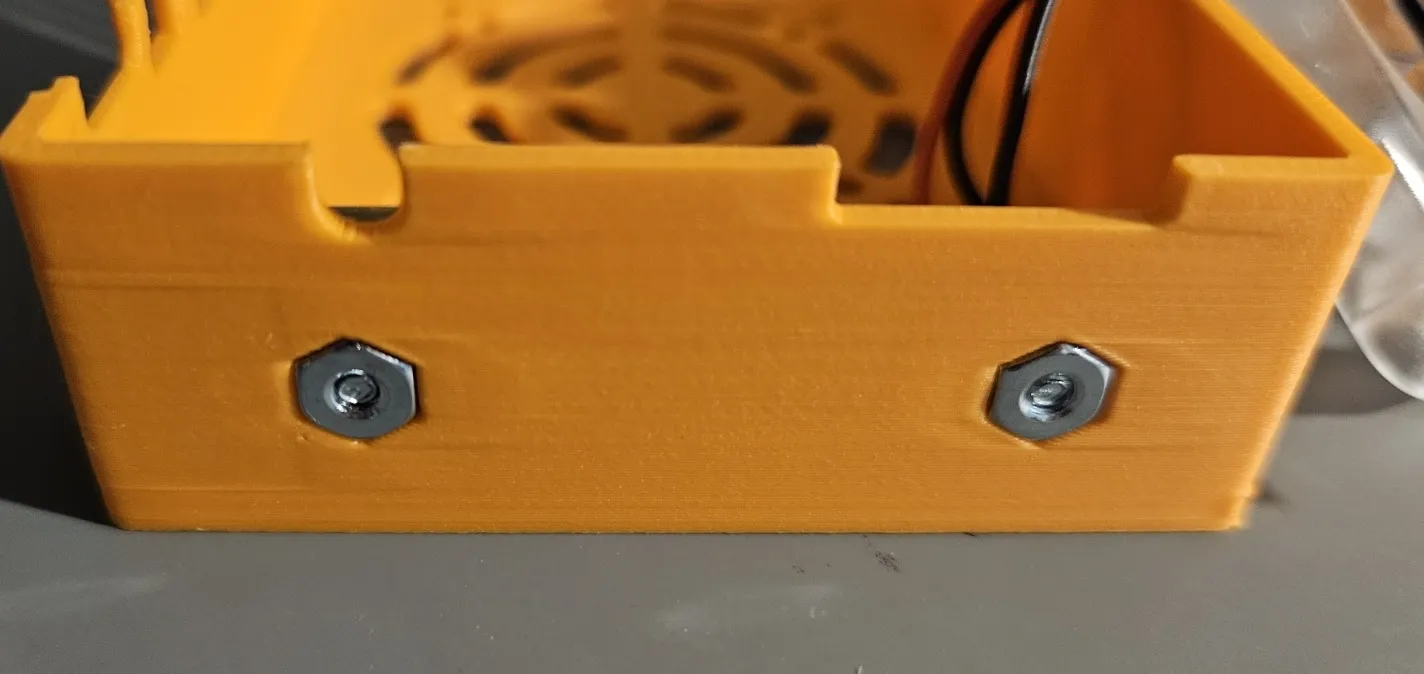
Finally, we can finish assembling the case. Using the two long 4-40 screws and nuts, put the cover on and fasten it together.
You should now have a fully functional Internal Zinc-V Case. Just apply 12V to the Zinc-V and it should work.
External Zinc-V Case Assembly
Section titled “External Zinc-V Case Assembly”Assembling the External style of case is very similar to the Internal case. The only differences are:
- 4-40 x 1-1/8” screws are used instead of 4-40 x 1-1/4”
- You will need an M2 nut for the locking feature
- You will not need the 2 4-40 x 1/4” screws or their associated nuts
- All steps related to the Zinc-V can be skipped
- The fan can be plugged into the Orange Pi header
- A fan is not strictly necessary but it is recommended.
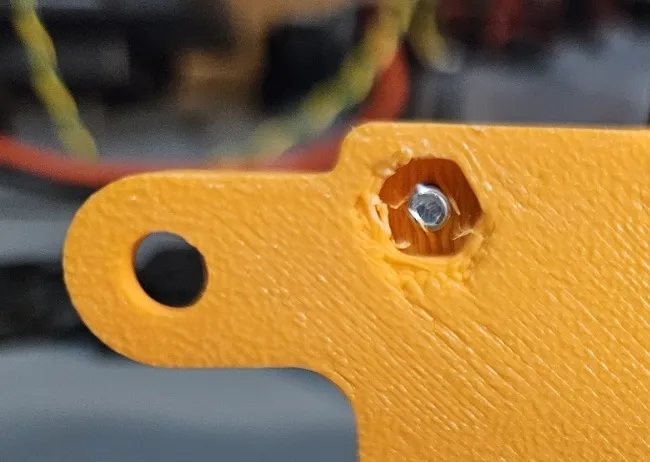
The M2 nut should be installed into the pocket like so:
The nut can be glued in or held in with a small piece of duct tape. If you use tape, you’ll need to poke a hole in it so that the screw can fit through.